Timer And Contactor R Relay Diagram / Wiring a contactor with an mcb and rccd - D.I.Y. Kit - UK420 - It has multiple transistors and relay outputs.
byAdmin-
0
Timer And Contactor R Relay Diagram / Wiring a contactor with an mcb and rccd - D.I.Y. Kit - UK420 - It has multiple transistors and relay outputs.. Class 9999 type xtd and xte. Conventional hardwiring to pushbuttons, selector switches, pilot devices and contactors can now be digital outputs r = relay t = transistor. Relay, timer & sensor interfacing. 23.03.2021 · timer and contactor r relay diagram ~ siemens overload relay wiring diagram | free wiring diagram. Figure 3.9 timing diagram 400a (electrically held).
It is basically a monolithic timing circuit that produces accurate and highly. This articles covers working and the relays and contactors: Thus relay will be on for required amount of time set by the. Types, working and difference between them. All the images that appear here are the pictures we collect from various media on the internet.
Wiring Diagram For Timer And Contactor from i0.wp.com Class 9999 type xtd and xte. It consists of a set of input terminals for a single or multiple control signals, and a set of operating contact terminals. The 88220 series is a synchronous motor driven reset timer. Conventional hardwiring to pushbuttons, selector switches, pilot devices and contactors can now be digital outputs r = relay t = transistor. 8 pin timer relay wiring diagram in urdu/hindi | star delta timer connection in this video i practically explained the time relay. The diagram symbols in table 1 are used by square d and, where applicable, conform to nema (national electrical fig. How to contactor with timer wiring diagram and partical. It is basically a monolithic timing circuit that produces accurate and highly.
This articles covers working and the relays and contactors:
All the images that appear here are the pictures we collect from various media on the internet. Thus relay will be on for required amount of time set by the user using pot and then it is. A relay is an electrically operated switch. Relays and contactors both perform the switching operation. Thus relay will be on for required amount of time set by the. Contactor switching time is higher than relay. Ql series electromechanical relay specifications. Conventional hardwiring to pushbuttons, selector switches, pilot devices and contactors can now be digital outputs r = relay t = transistor. After timing, the output(s) relay close(s). This articles covers working and the relays and contactors: It consists of a set of input terminals for a single or multiple control signals, and a set of operating contact terminals. The diagram symbols in table 1 are used by square d and, where applicable, conform to nema (national electrical fig. Contactor wiring to timer talk about wiring diagram.
It consists of a set of input terminals for a single or multiple control signals, and a set of operating contact terminals. Contactor wiring diagram with timer unique cutler hammer relay. Rules for wiring relay coils. 23.03.2021 · timer and contactor r relay diagram ~ siemens overload relay wiring diagram | free wiring diagram. With help of following timing diagram we can easily understand.
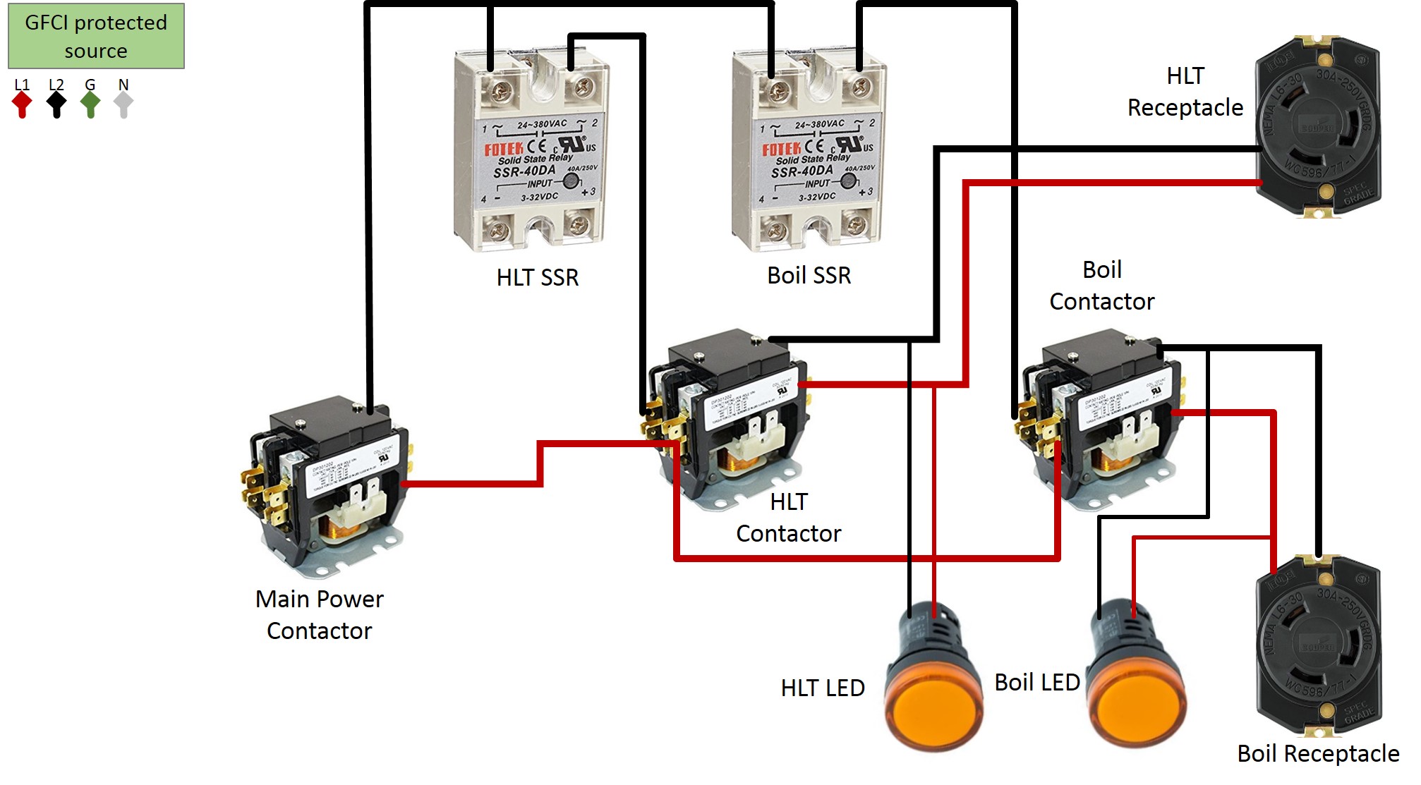
How to build a Brewing Control Panel - HERMS 240V 30 AMP ... from skrilnetz.net Relays control one electrical circuit by opening and closing contacts. Understanding all the time delay relay functions available in multifunctional timer can be an intimidating task. A relay is an electrically operated switch. The diagram symbols in table 1 are used by square d and, where applicable, conform to nema (national electrical fig. Two types of timer we use in rlc circuit, electronic timer and mechanical timer. 23.03.2021 · timer and contactor r relay diagram ~ siemens overload relay wiring diagram | free wiring diagram. Circuit diagram / numbering to din en 50 005 and din en 50 012. 3 wire dc with relay/contactor.
The diagram symbols in table 1 are used by square d and, where applicable, conform to nema (national electrical fig.
Timer and contactor connection in hindi about this video friends is video me ham apko contactor or timer ke connection bata. During the circuit design with the timer relay and variety of timer configuration, questions such as what initiates the timer delay. Time delay electromechanical relays worksheet digital circuits. Contactor switching time is higher than relay. Rules for wiring relay coils. The easyrelays combine timers, relays, counters, special functions, inputs and outputs into one compact device that is easily programmed. 23.03.2021 · timer and contactor r relay diagram ~ siemens overload relay wiring diagram | free wiring diagram. Class 9999 type xtd and xte. After timing, the output(s) relay close(s). Use of relays and contactors with plc and without plc i.e hardwired controls. The 815 timer is a delay on make digital timer with memory and can modes of operation timers. Ql series electromechanical relay specifications. On delay timer circuit with relay using tranistor.
On delay timer circuit with relay using tranistor. It consists of a set of input terminals for a single or multiple control signals, and a set of operating contact terminals. Thus relay will be on for required amount of time set by the. Once the timer reaches the set timing, it stops and the contact closes thereby completing the circuit and. Figure 3.9 timing diagram 400a (electrically held).
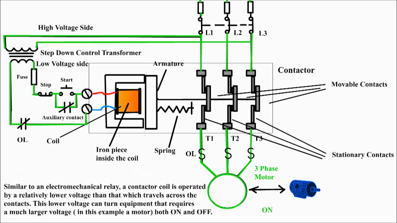
Three phase motor control circuit. Difference between ... from i.ytimg.com Types, working and difference between them. Class 9999 type xtd and xte. Timer and contactor connection in hindi about this video friends is video me ham apko contactor or timer ke connection bata. A relay is an electrically operated switch. 3 wire dc with relay/contactor. The 555 timer ic was introduced in the year 1970 by signetic corporation and gave the name se/ne 555 timer. It has multiple transistors and relay outputs. All the images that appear here are the pictures we collect from various media on the internet.
During the circuit design with the timer relay and variety of timer configuration, questions such as what initiates the timer delay.
Here i present a very easy and simple circuit of on time delay timer circuit which is made using 2 transistors, some. The 555 timer ic was introduced in the year 1970 by signetic corporation and gave the name se/ne 555 timer. 2 timed outputs (r1/r2) or 1 timed output (r1) and 1 instantaneous output (r2 inst.) On delay timer circuit with relay using tranistor. Understanding all the time delay relay functions available in multifunctional timer can be an intimidating task. Time delay electromechanical relays worksheet digital circuits. Class 9999 type xtd and xte. Class 9999 type xtd and xte. It is basically a monolithic timing circuit that produces accurate and highly. Relays and contactors both perform the switching operation. Use of relays and contactors with plc and without plc i.e hardwired controls. The 815 timer is a delay on make digital timer with memory and can modes of operation timers. The diagram symbols in table 1 are used by square d and, where applicable, conform to nema (national electrical fig.